A whole range of different structures is used offshore, depending on size and water depth. In the last few years, we have seen pure sea bottom installations with multiphase piping to shore, and no offshore topside structure at all. Replacing outlying wellhead towers, deviation drilling is used to reach different parts of the reservoir from a few wellhead cluster locations.
Some of the common offshore structures are:
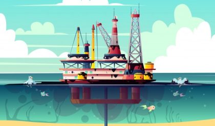
Shallow water complex, which is characterized by several independent platforms with different parts of the process and utilities linked with gangway bridges. Individual platforms include wellhead riser, processing, accommodations and power generation platforms. (This picture shows the BP Valhall complex.) Typically found in water depths up to 100 meters.

Gravity base consists of enormous concrete fixed structures placed on the bottom, typically with oil storage cells in a “skirt” that rests on the sea bottom. The large deck receives all parts of the process and utilities in large modules. Large fields at 100 to 500 meters of water depth were typical in the 1980s and 1990s. The concrete was poured at an onshore location, with enough air in the storage cells to keep the structure floating until tow-out and lowering onto the seabed. The picture shows the world’s largest GBS platform, Troll A, during construction.

Compliant towers are much like fixed platforms. They consist of a narrow tower, attached to a foundation on the seafloor and extending up to the platform. This tower is flexible, as opposed to the relatively rigid legs of a fixed platform. Flexibility allows it to operate in much deeper water, as it can absorb much of the pressure exerted by the wind and sea. Compliant towers are used between 500 and 1,000 meters of water depth.
Floating production, where all topside systems are located on a floating structure with dry or subsea wells. Some floaters are:
FPSO: Floating Production, Storage and Offloading. Their main advantage is that they are a standalone structure that does not need external infrastructure such as pipelines or storage. Crude oil is offloaded to a shuttle tanker at regular intervals, from days to weeks, depending on production and storage capacity. FPSOs currently produce from around 10,000 to 200,000 barrels per day. An FPSO is typically a tanker type hull or barge, often converted from an existing crude oil tanker (VLCC or ULCC). Due to the increasing sea depth for new fields, they dominate new offshore field development at more than 100 meters water depth.
The wellheads or subsea risers from the sea bottom are located on a central or bow-mounted turret, so that the ship can rotate freely to point into wind, waves or current. The turret has wire rope and chain connections to several anchors (position mooring – POSMOOR), or it can be dynamically positioned using thrusters (dynamic positioning – DYNPOS). Most installations use subsea wells. The main process is placed on the deck, while the hull is used for storage and offloading to a shuttle tanker. It may also be used for the transportation of pipelines.
FPSOs with additional processing and systems, such as drilling and production and stranded gas LNG production are planned.


A variation of the FPSO is the Sevan Marine design. This uses a circular hull which shows the same profile to wind, waves and current, regardless of direction. It shares many of the characteristics of the ship-shaped FPSO, such as high storage capacity and deck load, but does not rotate and therefore does not need a rotating turret.
Tension Leg Platform (TLP – left side in picture) consists of a structure held in place by vertical tendons connected to the sea floor by pile-secured templates. The structure is held in a fixed position by tensioned tendons, which provide for use of the TLP in a broad water depth range up to about 2,000m. The tendons are constructed as hollow high tensile strength steel pipes that carry the spare buoyancy of the structure and ensure limited vertical motion.
Semi-submersible platforms (front of picture) have a similar design but without taut mooring. This permits more lateral and vertical motion and is generally used with flexible risers and subsea wells. Similarly, Seastar platforms are miniature floating tension leg platforms, much like the semisubmersible type, with tensioned tendons.

SPAR consists of a single tall floating cylindrical hull, supporting a fixed deck. The cylinder does not, however, extend all the way to the seabed. Rather, it is tethered to the bottom by a series of cables and lines. The large cylinder serves to stabilize the platform in the water and allows for movement to absorb the force of potential hurricanes. SPARs can be quite large and are used for water depths from 300 up to 3,000 meters. SPAR is not an acronym and is named for its resemblance to a ship’s spar. SPARs can support dry completion wells but are more often used with subsea wells.

Subsea production systems are wells located on the sea floor, as opposed to the surface. As in a floating production system, the petroleum is extracted at the seabed, and is then “tied-back” to a pre-existing production platform or even an onshore facility, limited by horizontal distance or “offset.” The well is drilled by a movable rig and the extracted oil and natural gas is transported by undersea pipeline and riser to a processing facility. This allows one strategically placed production platform to service many wells over a reasonably large area. Subsea systems are typically used at depths of 500 meters or more and do not have the ability to drill, only to extract and transport. Drilling and completion is performed from a surface rig. Horizontal offsets of up to 250 kilometers/150 miles are currently possible. The aim of the industry is to allow fully autonomous subsea production facilities, with multiple wellpads, processing, and direct tie-back to shore.

Comments are closed.