Process control systems
A process control system is used to monitor data and control equipment on the plant. Very small installations may use hydraulic or pneumatic control systems, but larger plants with up to 250,000 signals to and from the process require a dedicated distributed control system. The purpose of this system is to read values from a large number of sensors, run programs to monitor the process and control valves, switches etc. to control the process. Values, alarms, reports and other information are also presented to the operator and command inputs accepted.
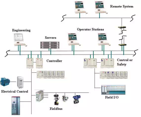
Process control systems consist of the following components:
Ø Field instrumentation: sensors and switches that sense process conditions such as temperature, pressure or flow. These are connected over single and multiple pair electrical cables (hardwired) or communication bus systems called fieldbus.
Ø Control devices, such as actuators for valves, electrical switchgear and drives or indicators are also hardwired or connected over fieldbus.
Ø Controllers execute the control algorithms so that the desired actions can be taken. The controllers also generate events and alarms based on changes of state and alarm conditions, and prepare data for operators and information systems.
Ø A number of servers perform the data processing required for data presentation, historical archiving, alarm processing and engineering changes.
Ø Clients, such as operator stations and engineering stations, are provided for human interfaces to the control system.
Ø The communication can be laid out in many different configurations, often including connections to remote facilities, remote operations support and other similar environments.
The main function of the control system is to make sure the production, processing and utility systems operate efficiently within design constraints and alarm limits. The control system is typically specified in programs as a combination of logic and control function blocks, such as AND, ADD and PID. For a particular system, a library of standard solutions such as level control loops and motor control blocks are defined. This means that the system can be specified with combinations of typical loop templates, consisting of one or more input devices, function blocks and output devices. This allows much if not all of the application to be defined based on engineering databases and templates rather than formal programming.
The system is operated from a central control room (CCR) with a combination of graphical process displays, alarm lists, reports and historical data curves. Smaller personal screens are often used in combination with large wall screens as shown on the right. With modern systems, the same information is available to remote locations such as onshore corporate operations support centers.
Field devices in most process areas must be protected to prevent them from becoming ignition sources for potential hydrocarbon leaks. Equipment is explosive hazard classified, e.g., as safe by pressurization (Ex.p), safe by explosive proof encapsulation (Ex.d) or intrinsically safe (Ex.i). All areas are mapped into explosive hazard zones from Zone 0 (inside vessels and pipes), Zone 1 (risk of hydrocarbons), Zone 2 (low risk of hydrocarbons) and Safe Area.
Beyond the basic functionality, the control system can be used for more advanced control and optimization functions. Some examples are:
• Well control may include automatic startup and shutdown of a well and/or a set of wells. Applications can include optimization and stabilization of artificial lift, such as pump off control and gas lift optimization.
• Flow assurance ensures that the flow from wells and in pipelines and risers is stable and maximized under varying pressure, flow and temperatures. Unstable flow can result in slug formation, hydrates, etc.
• Optimization of various processes to increase capacity or reduce energy costs.
• Pipeline management modeling, leak detection and pig tracking.
• Support for remote operations, in which facility data is available to company specialists located at a central support center.
• Support for remote operations where the entire facility is unmanned or without local operators full or part time, and is operated from a remote location.

Comments are closed.